| Description |
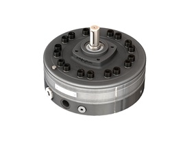
| Radial piston arrangement, with 5 or 7 pumping elements. External mounting type. Face mounting, Valve controlled, Fixed delivery. Bi-directional rotation of shaft. Available with extension shaft for through drive. With extension bracket assembly for coupling a low pressure pump having standard flange. |
|
| Section |
| Unit Dimensions |
| Technical Specifications |
| Designation .......................................... | 11RC basic radial piston pump group |
| Design ................................................. | Radial piston, valve controlled |
| No. of pistons ....................................... | 5 or 7 ; depending upon the flow requirement |
| Mounting .............................................. | Face mounting |
| Direction of rotation .............11RC.......... | Can be run in either direction |
| ....................................... 11RCE.......... | Depends upon the direction of rotation of pump attached. |
| Connection ....................Suction ........... | G 3/4 female
Suction head -- The oil level can be max. 300
mm below the suction port of the pump. Suction pipe size -- 25 o. d. x 2 th. (as far as possible use straight pipe) |
| .................................... Delivery ........... | G 1/2 female. |
| Suction Pressure ................................. | 0.02 to 3 bar positive. |
| Speed range ......................................... | 1000 to 2000 rpm. |
| Hydraulic medium ................................. | Mineral oil |
| Viscosity range ..................................... | 10 to 100 cSt. |
| Temperature range ................................ | -10 °C to +80 °C. (Do not exceed viscosity limits at extreme temperatures for efficient running of the pump) |
| Fluid cleanliness requirement ................. | As per ISO Code 16/13 |
| Performance ......................................... | Refer Table No. 1 |
| Mass ................................................... | 26 kg. |
Table No. 1
Code No. |
Geometrical displacement CC / REV |
Rated output at 1450 rpm |
Rated output at 1450 rpm & 95% efficiency |
Operating pressure bar |
Input power requirement (@ 1450 rpm) |
|||||||||||||||||
50 bar |
100 bar | 150 bar | 200 bar | 250 bar | 300 bar | 315 bar | 350 bar | 400 bar | ||||||||||||||
| KW | Hp | KW | Hp | KW | Hp | KW | Hp | KW | Hp | KW | Hp | KW | Hp | KW | Hp | KW | Hp | |||||
5A |
7.7 | 11.2 | 10.6 | 400 |
1 | 1.4 | 2.1 | 2.8 | 3.1 | 4.2 | 4.1 | 5.6 | 5.1 | 7 | 6.2 | 8.4 | 6.5 | 8.8 | 7.2 | 9.8 | 8.2 | 11.1 |
7A |
10.8 | 15.7 | 14.9 | 400 |
1.4 | 2 | 2.9 | 3.9 | 4.3 | 5.9 | 5.8 | 7.8 | 7.2 | 9.8 | 8.7 | 11.8 | 9.1 | 12.3 | 10.1 | 13.7 | 11.5 | 15.7 |
5B |
10.1 | 14.7 | 14 | 315 |
1.4 | 1.8 | 2.7 | 3.7 | 4.1 | 5.5 | 5.4 | 7.3 | 6.8 | 9.2 | 8.1 | 11 | 8.5 | 11.6 | ||||
7B |
14.1 | 20.5 | 19.5 | 315 |
1.9 | 2.6 | 3.8 | 5.1 | 5.7 | 7.7 | 7.5 | 10.2 | 9.4 | 12.8 | 11.3 | 15.4 | 11.9 | 16.1 | ||||
5C |
12.7 | 18.5 | 17.6 | 250 |
1.7 | 2.3 | 3.4 | 4.6 | 5.1 | 6.9 | 6.8 | 9.2 | 8.5 | 11.5 | ||||||||
7C |
17.8 | 25.8 | 24.5 | 250 |
2.4 | 3.2 | 4.7 | 6.4 | 7.5 | 9.7 | 9.5 | 12.9 | 11.9 | 16.1 | ||||||||
Note : The first digit in the code No. indicates No. of
pumping elements in the pump. The second letter indicates flow and pressure rating of the
pumping elements.
Code No. 7C for example, indicates a pump with 7 pumping elements having rated flow of
24.5 l / min and operating pressure upto 250 bar.
| Accessories |
Extension shaft
(For through drive)
Dimensions
Note : Torque limitation - The sum of torque used for the piston pump and torque used at extended shaft end should not exceed 148 Nm ( 22.2 kw @ 1450 rpm )
|
PRIMING PROCEDURE FOR CLOSED EXECUTION PUMP |
|
| A] When the Casing Pump is mounted Horizontally. | |
|
|
|
Case
I :
When
the pump suction port height exceeds 300 mm above oil level.
Case II: When the pump suction port height is less than 300 mm above oil level.
|
|
| B] When the Casing Pump is mounted Vertically | |
|
|
Case I:
When the casing pump is immersed
in oil.
|
|
|
Case II:
When the oil level is below the
suction port (i.e up to a distance of 300mm. Maximum).
|
| Note:-- Priming is not required to be done every time you start the pump after short durations (a day or two) of non-operation. | |
| Suction pipe specification | |
|
1) 1R-series :-- 16 O.D.x 2 mm thick
(Preferably straight) for Single row pump. 2) 2R-series :-- 25 O.D.x 2 mm thick (Preferably straight) for Double row pump. 3) 11R-series :-- 25 O.D.x 2 mm thick (Preferably straight) for Single row pump. 4) 12R-series :-- 30 O.D.x 2 mm thick (Preferably straight) for Double row pump. |
|
| Check valve model codes ( To be ordered separatly) | |
|
1) 1R-series :-- C10T0-03 2) 2R-series :-- C15T0-04 3) 11R-series :-- C20T0-03 4) 12R-series :-- C20T0-03 |
|
| Ordering Informations |

| Note : | For Bell housing assembly Refer Sheet
No. p09035. For Extension bracket assembly Refer Sheet No. p09090. |
| All rights reserved. Subject to revision. |
|
|
|
|
|
Regd. office & Works : |
|
Copyright ©
Polyhydron Pvt. Ltd. Belgaum, India. |
Updated on May 13, 2010 02:30 pm .